Výzkum
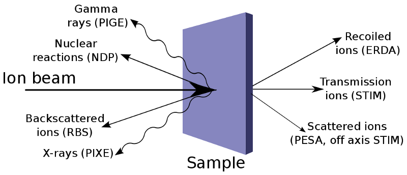
Ion beam analytical methods is a cluster of analytical techniques that use an ion beam for study of structures and composition of samples. The beam of the accelerated ions is applied for the surface modification of solids and for the analysis of their composition and structure. Ion beams are produced by a particle accelerator. The individual IBA techniques are distinguishable by the different types of interaction of ion beam and solid target. These methods have several unique characteristics which couldn't be substituted for other alternative approaches.
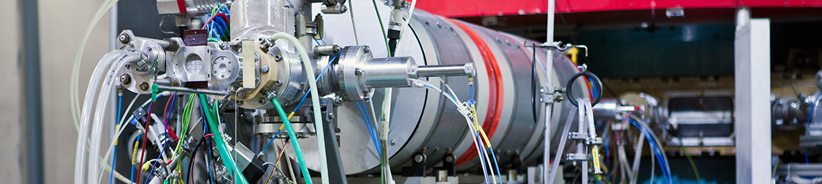
In department we use 3 MV electrostatic accelerator Tandetron 4130 MC on these purposes. In the last 10 years several equipments for analytical methods were assembled, such as: PIXE, RBS, ERDA, PIGE, NRM. Group of Nuclear Analytic Methods systematically partake in the study of synthesizing, structure and properties of advanced materials for microelectronic, optic, optoelectronic, cryogenic and materials with exclusive properties (micro-hardness, chemical resistance, bio-compatibility, etc.). Surface structures and systems prepared in cooperation with Czech and foreign institutes by different methods (epitaxial grow, Czochralsky's method, ion implantation, deposition of plasma polymer, CVD, PCVD, magnetron sputtering, etc.) are analyzed in our laboratory with different analytical methods. Group of Nuclear Analytic Methods systematically partake in the study of synthesizing, structure and properties of advanced materials for microelectronic, optic, optoelectronic, cryogenic and materials with exclusive properties (microhardness, chemical resistance, biocompatibility, etc.).
Nuclear analytic methods have been developed and extensively used in the NPI since the early 60s of the last century. In particular, neutron activating analysis and prompt methods of analysis with charged particles beam and beam of neutrons was handled. During the past period several analytical methods were innovated, practical experience of their application was obtained in collaboration with many Czech and foreign scientific enterprises and organizations.
Video
Recent research results (presentation in English, voice commentary in Czech):
Research topics
The main field is the application of nuclear physics and physics of ionizing radiation in the field of synthesis, modification and analysis of progressive materials. Scientific activities include the application of energetic ion beams for surface and volume modifications of materials by ion implantation and irradiation, ion lithography with focused beams, single ion irradiation for the creation of micro and nanostructures with specific functional properties and applications in electronics, optoelectronics , waveguide optics, flexible microelectronics, sensors and bionics, for specific applications in microfluidic, biologically and optically active microstructures and others.
We are preparing new materials, structures, composite layers, nano and microstructured materials based on semiconductor crystals, glasses, polymers, polymer composites with nanoparticles and 2D materials in cooperation with a number of Czech (MFF UK, ICT Prague, Masaryk University, Institute of Plasma Physics ASCR, UJEP etc.) and foreign (BAM Berlin, Germany, HZDR Dresden-Rossendorf, Germany, University of Messina, Italy, IFIN HH, Bucharest, Romania, University of Oslo, Norway and others) workplaces.
Part of the scientific work is the preparation of new materials, followed by their characterization by ion beam analytical methods, which provide non-destructive depth element mapping, qualitative and quantitative analysis with high sensitivity and in some cases isotopically specific quantitative analysis of materials. Part of the scientific content is also the study of solids degradation due to radiation damage, analysis and simulation of emerging radiation defects, as well as the study of energy losses of energetic ions in various types of materials.
Structures and systems prepared in cooperation with our and foreign workplaces are studied using high-energy ion beams by standard methods RBS (Rutherford Backscattering Spectrometry), ERDA (Elastic Recoil Detection Analysis), PIXE (Particle Induced X-ray Emission spectroscopy) etc. on the accelerator Tandetron in NPI. We also focus on the development of innovative ionic analytical methods in our lab - RBS-channeling, PIXE-channeling - applicable for the study of crystalline materials, for structural studies, positioning of dopants in crystals, etc. RBS-channeling and ERDA-TOF methods are unique in the Czech Republic. The Time of Flight (TOF) charged particle spectrometer, design and commissioning was completed in 2007. The RBS channeling instrument was built and commissioned in 2010. For the last 5 years, our team and also focused on strengthening the theoretical basis for our experiments. We perform simulations of ion channeling phenomena, ion transmission and backscattered particle 2D map simulations in different crystallographic orientations of crystals of different type and quality, simulation of dopant positions in crystalline materials depending on experimental data using FLUX program, etc.
Ion Implantation / Irradiation:
| Parameter | Description |
|---|---|
| Ion species | selected ions (typically H, He, Li, O, C, Si, Cu, F, Ag, Au, W and upon the request except noble gasses, lathanides, radioisotopes |
| Ion energy | 600 keV - 30 MeV depending on ion species |
| Depth range | 100 nm - several µm depends on ion energy |
| Fluence | 107 - 1016 cm-2 |
| Incidence angle | Standard 0°, 7°; others on request |
| Beam current | nA - µA |
| Sample size | Small pieces (cm2) Ø 80 mm |
| Temperature | Liquid nitrogen - 1100°C, RT, heating stage up to 600°C |
| Special features | quandrupole mass spectrometry; external beam irradiation of biological samples, volatile samples etc. |
Ion Beam Analysis:
| Method | Elements | Detection limit [at%] | Resolution depth | Resolution lateral |
|---|---|---|---|---|
| RBS | O - U | 1 | 10 nm | 0.5 mm |
| RBS and PIXE- Channelling | crystalline structure study and dopant positioning | 1 | 10 nm | 0.5 mm |
| ERD with He | H, D, T | 0.1 | 30 nm | 1.5 mm |
| ERDA TOF | H-S | 0.1 | 15 nm | 1.5 mm |
| PIXE | Al-U | ppm | not applicable | 1 mm |
| µ-Probe with RBS, PIXE, PIGE |
1 µm | |||
| PIGE | B, Li, Na, F, P, Al, … | 1-1000 ppm | not applicable | mm |
| STIM | internal structure in thin samples | not applicable | not applicable | 0.3 µm |
| PESA | H in thin samples | 0.1 | not applicable | 1 µm |
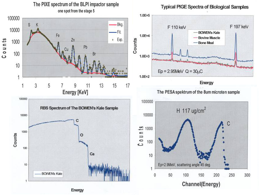
Rutherford Backscattering spectrometry (RBS) is most commonly used non-destructive nuclear analytical methods. RBS is widely used for study of thin layers and for study of multilayer systems with thickness from nm to µm. RBS is very suitable for elemental depth analysis. From such measurement it is possible to determine, with some limitations, both the atomic mass and concentration of elemental target constituents as a function of depth below the surface.
Measurement with this method may be performed on amorphous as well as crystalline materials. It involves measurement of the numbers and energy distribution of energetic ions (usually MeV light ions such He+) backscattered from atoms within the near-surface region of solid targets. Ions for RBS are usually light ions (H+, He+) with energy units MeV.
Energy of backscattered ions, which we detect, is connected with energy loss in scattering on the elements nucleus and with the energy loss of ions between passing through the sample. The RBS detection limit is between 1011 – 1015 at.cm-2. RBS depth resolution is an average of 5 nm.
Features of RBS: 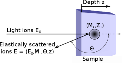
- high sensitivity for heavy elements on a light substrates
- good detection sensitivity for light elements in a heavy matrix only in special cases
- good depth resolution (average 5 nm)
Parameters of RBS:
- ions: H+, He+
- energy of ions: order of MeV
- detection limit: up to 1mg/g
- depth range: about micrometer
Theory of RBS
Sample is irradiated with light ions (usually 2-3 MeV (H+or He+)) and the elastically backscattered projectiles at large angles are detected. The mass of the target atoms could be identified from the energy of the backscattered projectile. The backscattered particles are detected by the semiconductor detectors Si(Au), the accessible depth 2-10 mm. The heavy element detection limit in the light matrix is up to 1mg/g. The lower mass causes higher transferred energy. The mass resolution is given by detector energy resolution, the energy and projectile mass. The ussage of heavier ions enables us to reach the mass resolution DM<2.

Elastic Recoil Detection Analysis (ERDA) is a non-destructive nuclear analytical method. ERDA is a technique for depth profiling of light elements in thin layers and in multilayer systems. Measurement with this method may be performed on amorphous as well as crystalline materials. ERDA uses high energy (~1MeV/amu) heavy-ion beams to kinematically recoil and depth profile low atomic number target atoms. The heavy ion projectile only needs to have a greater mass than the target atom. Alpha particles are commonly used to obtain recoil spectrum for hydrogen and its isotopes.
Features of ERDA: 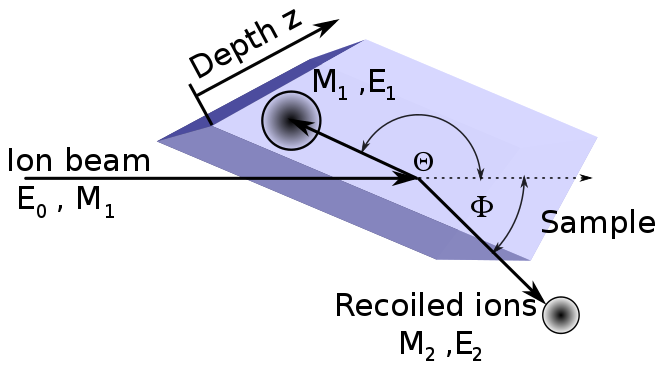
- good sensitivity for light elements
- wors mass resolution
- good depth resolution (average 10 nm)
Parameters of RBS:
- ions: He+ and heavy ions
- energy of ions: order of MeV for He+ and order of 10 MeV for heavy ions
- detection limit: 1mg/g
- depth range: order 100 nm
Time of flight ERDA
The mass-depth ambiguity can complicate the interpretation of ERDA spectra. This ambiguity results because the energy of the recoiled ions depends on the mass and depth of the target atom in the sample. Here is a benefit of Time of flight - ERDA (TOF-ERDA), the recoil ion energy and mass we can measured independently. TOF-ERDA measured simultaneous the velocity and energy of the recoiled atoms from the target. The velocity of recoil atoms is determined by measuring the time required to pass between two thin foils at TOF1 ad TOF2 with a corresponding TOF distance. As the atoms passes through the foil, secondary electrons are ejected and accelerated into detector to mark a timing event.
Ions for TOF-ERDA ranging from O to Au at tens of MeV.


RBS-channeling spectrometry - enables us to investigate crystalline materials. RBS channeling is based on channeling of charged particles in single crystalline structure and back-scattered ion yields in the spectra when the beam is parallel to crystallographic orientation axis can give us information about the damage and disorder depth profiles, dopant positioning and damage depth accumulation. For RBS channeling are typically used ion beams of 1-2 MeV He+ ions.
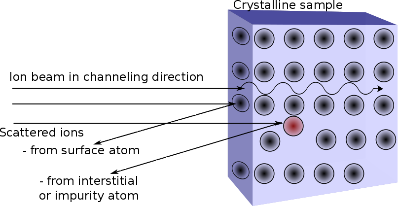
Simultaneous acquisition of back-scattered ions and induced X-ray emitted via RBS and PIXE detectors depending on impinging ion beam angle can give us comprehensive information about even lighter dopant positions in heavy element matrix.


 scans on lithium niobate")

Particle Induced X-Ray Spectroscopy (PIXE) is a very sensible non-destructive ion beam analytical method for elemental composition study. PIXE is very suitable for a study of area and bulk concentration of elements not for depth analysis. Basees for this method is that the high energetic proton beam excites, due to inner-shell ionization, the emission of characteristic X-rays from the sample atoms. Particle Induced Gamma-ray Spectroscopy (PIGE) is a versatile technique, which complements other ion beam techniques (especially PIXE) for sample analysis. It is the most common application of nuclear analysis. The PIGE method is mostly based on nuclear reactions (p, g), (p,p´g), (p, a g) induced by MeV protons, where prompt nuclear gamma-rays are produced. PIGE is very suitable for light elements analysis.
In the true sense, PIXE is not a nuclear technique, since the ionisation of the atoms by the ion beam and the subsequent emission of characteristic X-rays are purely atomic electromagnetic processes. Great benefit of PIXE is possibility of measurement at atmospheric pressure. 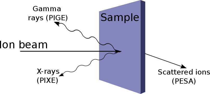
Features of PIXE and PIGE:
- high sensitivity
- measurement at atmospheric pressure
Parameters:
- ions: H+
- energy of ions: order of MeV
- detection limit: up to 100 ppm (PIXE), 1000 ppm (PIGE)
- depth range: order of ten micrometer
Basic idea of this method is focusing of a ion beam on the smallest dimension and scanning on the sample. Ion beam analytical methods are the same as with normal dimensions – classical ion beam methods (RBS, PIXE, PIGE). Ion micro-beam is versatile equipment that allows study of structures with resolution of microns. Compared to electron micro-beam have better detection limits and may study the trace quantity. Ion microbeam line with Oxford instruments focusing system is used for microstructuring of materials, 3D elemental mapping using ion microprobe (PIXE, PIGE, RBS), single ion beam irradiation, ion litography. The planned 3D litography instrument will upgrade significantly our analytical capabilities and it is prepared to be developed now. Ion beam micromashining, optical microstructure deposition in ion microprobe device together with possibility of the external beam nozzle. Structural studies of internal morphology is available via Scanning Transmission Ion Microscopy (STIM) analysis.
Ion lithography with 5MeV C ion beams creates super-microcapacitors

Optical microscopy image of super-microcapacitor prepared by C 5MeV ion beam lithography in a), scheme of the microcapacitor device in b)


The SEM top-view images of electrodes prepared using carbon ion-beam writing on the surfaces of PI a), PMMA b) and GO c). The DC current-voltage characteristics of the GO super-microcapacitor d)
3D elemental mapping in composites
PMDS composites with reduced graphene oxide (r-)GO and graphene (G) particles have been prepared by spin coating methods and investigated due to the prospective morphologies and internal structure being applicable in various scientific fields. The interior structure of the studied virgin PDMS and r-GO and G-PDMS composites has been investigated with Scanning Transmission Ion Microscopy (STIM). The evaluation of the energy loss of the beam passing though the PDMS composites provided information about the sample thickness. 2.7 MeV H+ beam was chosen because ions must penetrate the sample and the energy loss must be large enough to obtain good energy loss contrast and show structures at high resolution. The velocity of the energetic particles slows down because of the increase of the interaction cross-section with the surrounding atoms. We recorded proton intensity in transmission mode and visualised the interior morphology in various depths of hybrid PDMS composites using proton beam in microbeam mode providing scanning of the composite surface. Simultaneously, PIXE and RBS signal from the surface during microbeam scanning was detected. PIXE analysis with microbeam shows Si elemental distribution outside the pores in agreement with the pores morphology identified with STIM. It was possible to distinguish the bulk (colored areas) from the pores (black areas). RBS elemental maps give us information about carbon lateral distribution, where carbon is filling the pores in case of G-PDMS contrary to r-GO-PDMS. In SEM images visualized the morphology of porous hybrid composite; in the first column from the left side, the pores size and shape are clearly visible. In the central column the pores are showed in detail. In the third column it is possible to distinguish the size of the graphene nanoplatelets which look like powder f), of microplatelet of rGO i) while the texture of virgin PDMS c) appears compact and homogeneous. Complex characterization of promising graphene-polymer hybrid composites has been realized using our advanced ion microbeam instruments using compilation of STIM, RBS and PIXE analytical methods.

STIM images from various sample depth – from the surface up to 132 µm - of virgin PDMS a), d), g), i), r-GO-PDMS b), e), h), m) and G-PDMS c), f), i), n) at different depths

PIXE elemental map of Si from the surface of virgin PDMS in a) r-GO-PDMS b) and G-PDMS c)

RBS elemental map of C for virgin PDMS, r-GO-PDMS and G-PDMS on the surface in a), b) and c),respectively. RBS elemental map of C for virgin PDMS, r-GO-PDMS and G-PDMS in the bulk d), e) and f), respectively
Ion microprobe was applied on the microstructure deposited in polymers and glasses using heavy ion focused beams, which are unique experiments also in the European context; in collaboration with ATOMKI, Hungary.
3D elemental mapping including interior morphology study using PIXE, PIGE, RBS and STIM is used for the comprehensive characterization of complex polymer/GO/nanoparticle composites, imaging or irradiation of living cells, small animals for environmental studies as well as for complex characterization of cultural heritage samples.
Beam characteristic
| Objects slits to sample | 5m | |||
| Objects slits to collimator | 4m | |||
| Typical current | ||||
| Objects slits (openning alternativelly) | 20x80 µm2 | 40-50 pA | ||
| 30x120 µm2 | 70-100 pA | |||
| 40x160 µm2 | 100-200 pA | |||
| with sputter source | 60x240 µm2 | 50-100 pA | ||
| Collimator slits | 800x800 µm2 | |||
| Energy (standard) | 2 MeV | |||
| Other tested | from 0.8 MeV to 2.6 MeV (11.5 MeV for C4+) | |||
| Ions (tested) | H+, He+,C4+ | |||
| Typical brightness (2 MeV protons) | ||||
| Duoplasmatron | 0.4 pA/µm2 mr2 MeV | |||
| Cs sputter source | 0.1 pA/µm2 mr2 MeV | |||
Detailed information about microbeam parameters and applicability you can find here:
Performance and application of heavy ion nuclear microbeam facility at the Nuclear Physics Institute in Rez, Czech Republic, Rev. Sci. Instrum. 90, 013701 (2019); doi: 10.1063/1.5070121


Ion beam implantation is a process when accelerated ions are shooting into the solid. This methods is optimal for change of physical, chemical, electric or optic properties of the solid. Ion beam implantation is capable of preparation of layers with high density and good defined depth profile and for change of crystalline structure of substrate.
Application of ion beam implantation: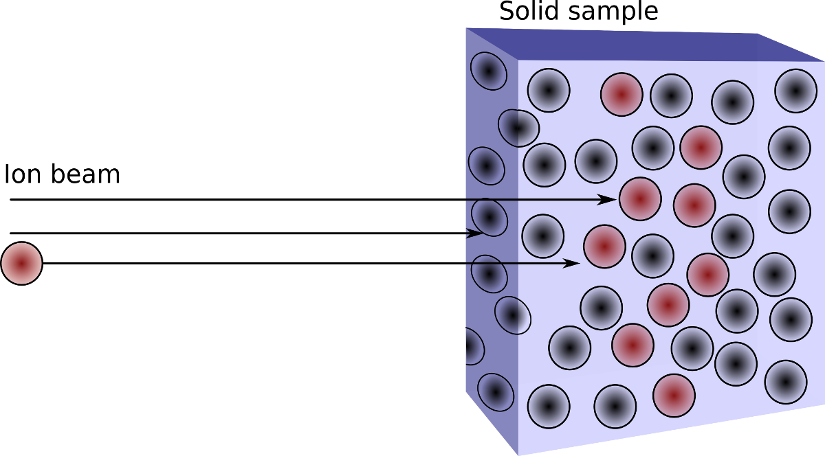
- doping of semiconductors
- doping of insulators with metal ions
- creation of nanoparticles
- change of electric and optic properties of solid


The typically produced ion beams available at Tandetron facility are provided in the table with the appropriate ion beam currents. The additionally requested ions for your experiments must be consulted with the instrument responsible and tested before the experiment will be proposed at Tandetron in the frame of CANAM.

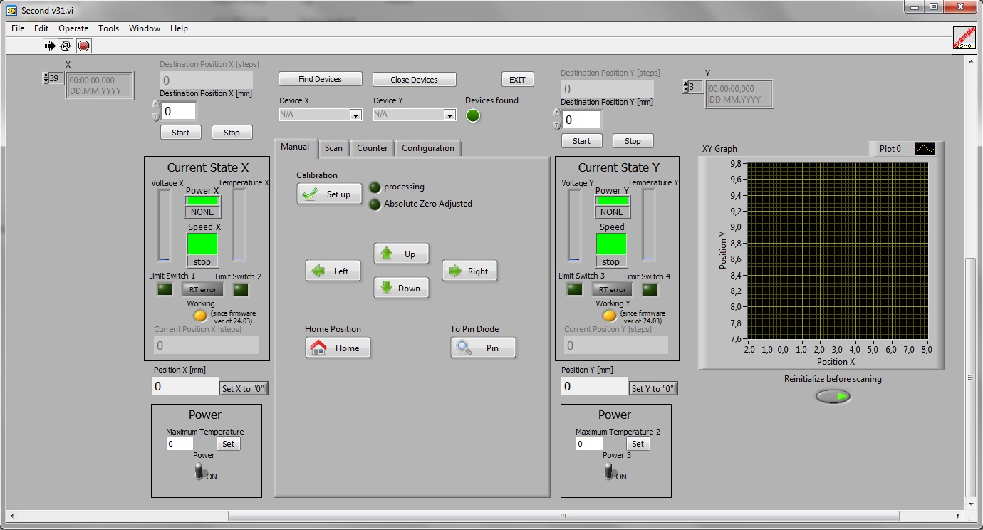
LabView code for automatic control of the four-axis manipulator designed for structural studies using nuclear analytical methods
Authors:
Ing. Jiří Novotný, A. Macková, P. Malinský
Annotation:
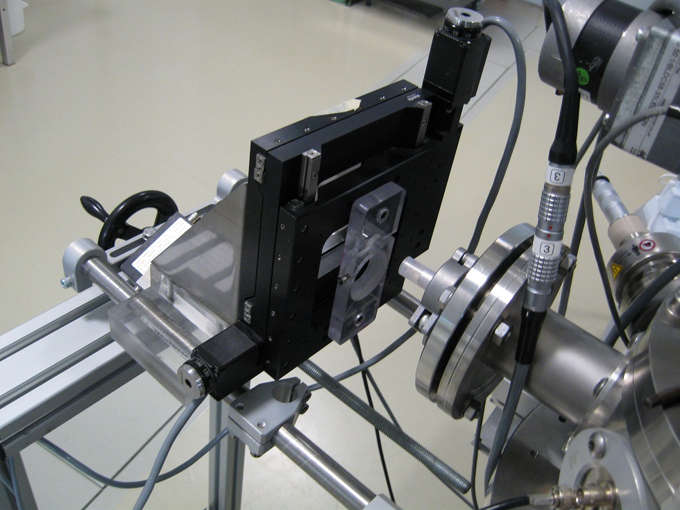
In the frame of instrumentation development for nuclear analytical methods was installed the sophisticated four-axis goniometer for sample manipulation. Structural studies using nuclear analytical methods need software which enables the automatized procedures of the movements for the finding of the main crystallographic orientations. The goniometer offers the lateral movements in two axes, measuring of the larger set of samples and the rotation around the horizontal and vertical axis. The movements of all four stepper motors can be used in both relative and absolute mode. To determine the absolute position of all axes are used in rotation position sensors and X and Y are used terminal micro switch. Position of all axes is graphically and numerically watched on a computer monitor. Motor movements can be carried out continuously or the movements are realized precisely to the given value with the precision 0.01°. The predefined geometrical arrangements can be used Zero-pos, TOF, ERDA, LOAD-LOCK, and RBS10 Thru and allow approaching the specific measurement position. In the frame of this code is it possible to use the automatized procedures of the crystalline material scanning with simultaneous measurement of the back-scattered ions (RBS) or X-rays (PIXE). Based on this scanning procedure we can find interactively the main crystallographic axis of the investigated crystalline sample and used it for the further structural study. Simultaneously, these positions are monitored virtual LEDs. The program is unique because the manipulator is designed especially for this purpose.
LabView program for surface resistivity measurements of samples
Authors:
Ing. Jiří Novotný, Ing. Pavel Horák, Václav Kučírek
Annotation:
The program is designed for the measurement of the sample sheet resistivity using the van der Pauw method, i.e. the 4-point resistivity measurement. The arrangement is designed for square samples with dimensions 15x15 and 12x12 mm. The program communicates with the switch, power source and voltmeter Keithley and calculates the surface resistance of the samples (see Appendix). The electric current set in the program is driven to 2 adjacent electrodes and voltage is measured on remaining 2 electrodes. The measurement is repeated with reversed polarity. Subsequently, the switch disconnects current setup and connects new set of contacts. The electrical current is driven in the same way and the voltage is measured. All 4 sides of the sample are being measured this way and 8 values of the resistance are obtained. From these values a value of sheet resistivity is calculated.
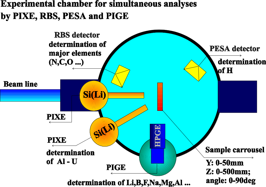
Automatic measuring system for simultaneous analysis PIXE, RBS, PIGE and PESA on LabWiew base for XIA digital modules Pixie4 and XMAP
Authors:
Ing. Jiří Novotný, RNDr. Havránek Vladimír CSc.
Annotation:
This Lab Wiew computer code enables both fully manual and automatic control over the IBA (Ion Beam Analysis) measurement (mainly individual or simultaneous measurements by PIXE, RBS, PIGE and PESA methods ) in multipurpose target chamber placed on the Tandetron 4130MC ion beam line +30o at INP ASCR. The cod controls adjustments of the samples into the measuring position by means of 4-axis manipulator. It communicates with XIA (Pixie4 and XMAP) digital modules and controls acquisition and visualization of spectra from up to 8 spectroscopic lines . The cod registers ion beam intensity and ion fluences during and after the measurement by means of inner and external beam monitor and check the sample position and condition after the measurement using digital camera. Finally, it controls the archiving of measured spectra and measurement condition in format suitable for subsequent analysis. This measuring system considerably improves and speed up the analysis , storage and arranging of measured data, and simplifies further spectral data evaluation. The cod is suitable, both for the individual sample measurement or for the measurement of large series of samples.
The system of corrective magnets
Authors:
V. Kučírek, J. Novotný, V. Semián
Annotation:
It is a system of corrective magnets with appropriate power source for correcting of the ion beam axis to achieve the optimal beam trajectory for passing through the collimator which axis does not correspond exactly with the geometry of the beam line. By this way it may be optimalized the beam direction into 4 different ion beam lines. Central control is possible from the PC via RS232 serial port.
LabView program for implantation to 12 samples and to center the beam during implantation
Authors:
Ing. Jiří Novotný, RNDr. Vladimír Havránek, CSc.
Annotation:
This is software dedicated for an automatic ion implantation of set of samples as an extension for an implantation chamber commercially manufactured by High Voltage Ltd. In the chamber, there is a manually rotated carousel for 12 samples and four Faraday cups are used for ion current measurements. Automatic sample implantation is realized using a stepping motor connected to the chamber; to indicate the sample in the implant position micro switches are used. The programme (written in LabView, Austin, USA) needs input data: the terminal voltage of the accelerator, ion charge and the required fluence ions/cm2, which is entered into a table for each sample. The programme calculates the implantation parameters for set input data and evaluates its viability as a electrostatic steering of ion beam in X and Y, the number of pulses of the integrator. Further, the program operates the Faraday Cup located in the beamline for the beginning and the end of the implantation. During implantation, the following values are displayed: ion energy, the estimated time of implantation, current (nA/cm2), real counts, implanted fluence (ions/cm2), the time until the end of implantation, the current position of the carousel and the LED display of the sample position. For the event of a shutdown status of the implantation is every minute written into a file. At the end of the implantation is the implantation protocol written into the same file.
For the positioning of the beam over the sample, the programme graphically shows the calculated location of four Faraday cups and determines the geometric centre, to which the sample for the implantation is placed.
This software improves significantly the implantation procedure; saving the processing time of the accelerator during the implantation. It does not require the presence of the operator, thus lowering the costs of the sample implantation.
LabView program for Profile Beam Monitor
Authors:
Ing. Jiří Novotný, RNDr. Vladimír Havránek, CSc.
Annotation:
The functional sample program is expanding the commercial Beam Profile Monitor from NEC Ltd. Originally, the monitor had to be connected to an oscilloscope and it was quite complicated to measure the ion beam profile. The program (written in Labview, Austin, USA) replaced the oscilloscope and the measurement became simpler and clearer. The programme displays peaks in planes X and Y, color-coded quantity of cutting axes X and Y, and the integral spectrum in X and Y.
Since it is not necessary to connect to the oscilloscope, the information about the shape and location of the ion beam is quickly graphically indicated, saving the operator time and the machine time of the accelerators.
Software for the positioning during the irradiation on the external beam
Authors:
Ing. Jan Vitner, M. Davidkova
Annotation:
SW is used for precise positioning of samples exposed to the ion beam radiation in the ambient atmpsphere. There is a positioning device driven by two electromotors, which are controlled by the developed SW. SW allows us to control the positioning device in precision about 0,001 mm in two axis, thus the areal scanning is available. Thus we are able to irradiate the samples, which can not be placed in vacuum conditions (e.g. living cells), with the defined mathematical procedure to cover the requested irradiation area homogeneously by ion beam with maximum beam spot 1 mm2 . We can choose the size of the area exposed to the radiation, to choose the quantity of the radiation (ion fluence) and to achieve uniform radiation of the sample with very low fluencies 104 iontů/cm-2.
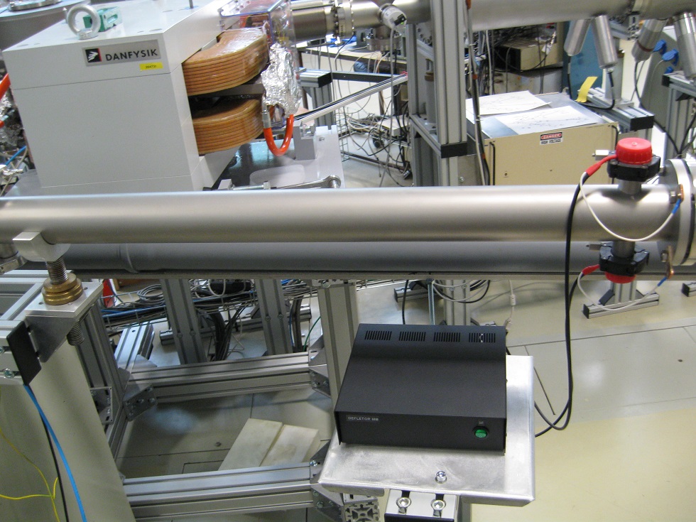
The gate of the ion beam
Authors:
Václav Kučírek, Vladimír Havránek RNDr., CSc., Vladimír Semián, Pavel Plocek
Annotation:
It is a source of pulses plus and minus one hundred volts with a very short rising and falling edge (less than 0.2 microseconds). Normally, the output is exactly at zero. Pulses can be of any length. The pulses are fed to the deflection plates. During the deflection the beam does not pass through the ion line but ends on the screens. Actuating: TTL signal.
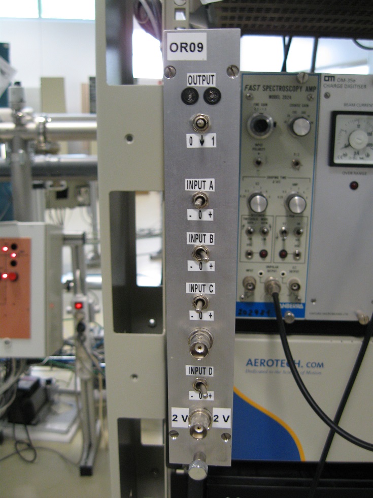
Indicator of neutron flux
Authors:
Václav Kučírek, Jiří Vacík Ing., CSc.
Annotation:
It is uni-module unit NIM comprising eight highly stable sources of spectrometric pulses with independently adjustable polarity and independently adjustable amplitude from zero to five volts. The device further includes a spectrometric amplifier and the related upper discriminator. From the output of the discriminator the output pulses are synchronized. To synchronize the output pulses is also possible to use external pulses or internal generator.
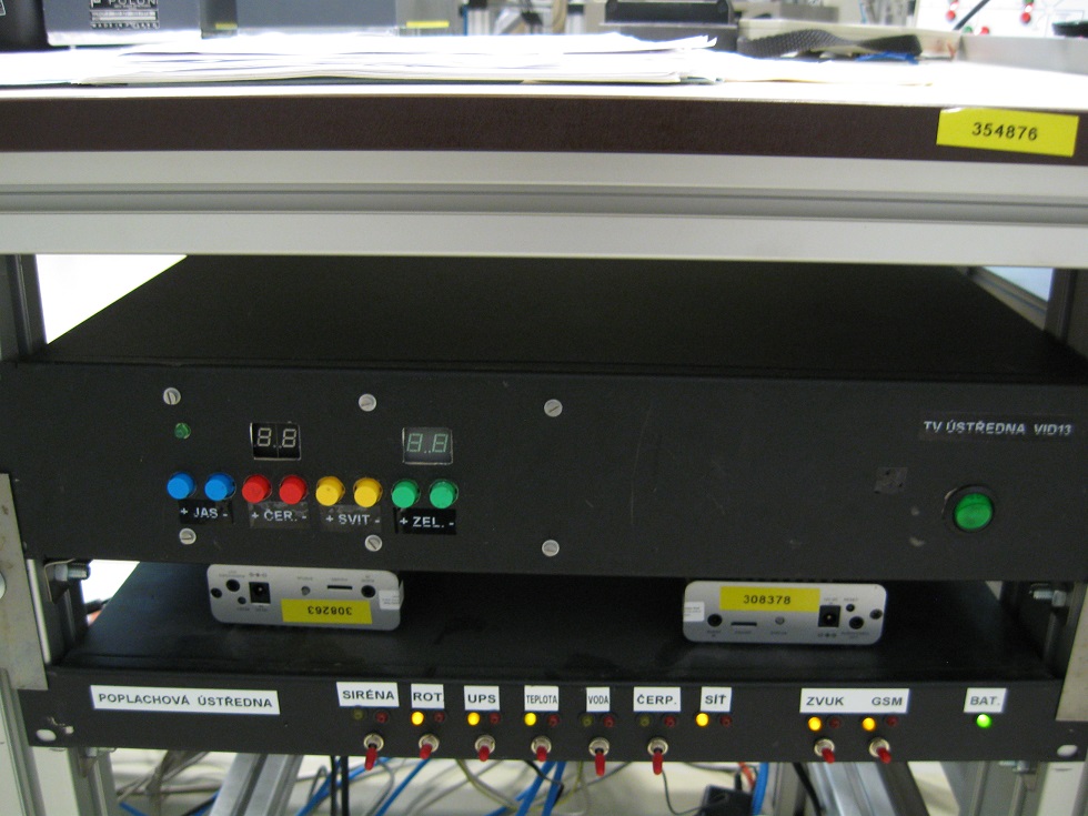
Internal television system
Authors:
J. Kučírek, J. Novotný, V. Semián
Annotation:
It is a closed television system for distributing signals from many cameras to two output channels, and also on several monitors. The system can be independently controlled from multiple locations including several lines RS232.
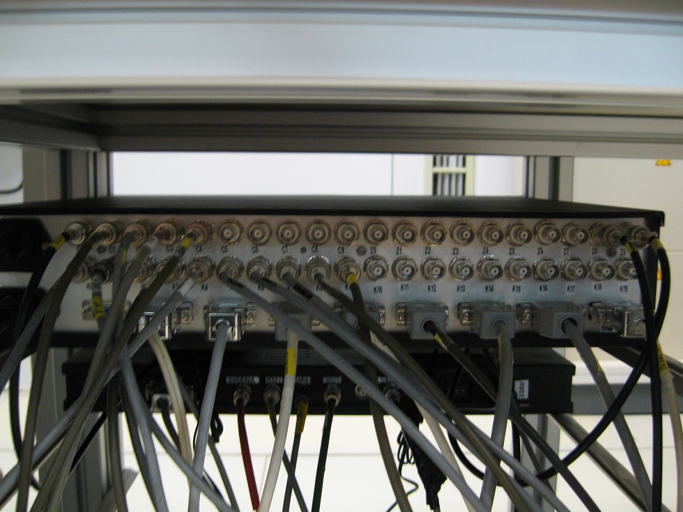
Beam Current Measuring System of the Shadowing Shields
Authors:
Ing. Jan Vitner, Václav Kučírek, Ing. Martin Švider, Pavel Plocek, Vladimír Semián
Annotation:
The system is used for the measuring of an accelerator beam of particles. There are four movable shields placed across the beam line in two rectangle axes in all directions. The beam can be falling to each of them by its small part. Each shield can evoke a current flowing between the shield and the developed measuring device. The device is able to measure the current flowing from each of those shields and the device is able to screen measured data by itself or the data could be send to an computer to be screened by a special program, which is an component of the whole developed system. Thanks to this system, we are able to center the beam. The output information is the value of the current flowing from each shield, which represents the value of the charge fallen to the current shield.
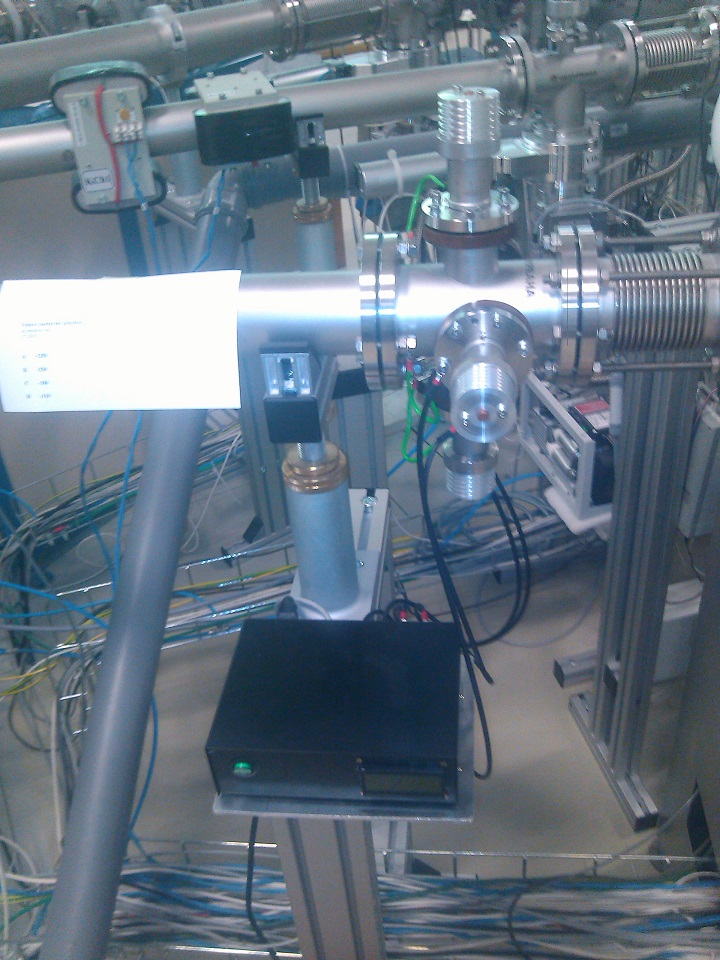
Microbeam chamber
On the backside of the microprobe interaction chamber a flange for external ion irradiation is mounted. The flange has a nozzle with a 200 nm thick silicon nitride window. The window is strong enough to withstand the pressure drop and allows minimizing both beam shape lateral straggling and energy dissipation due to small thickness. This material is widely used in transmission electron microscopy because of good radiation hardness and mechanical resistance.
The end-stage for external ion beam irradiation is constructed on the metal frame. Samples are fastened on a motorized XY scanning stage manufactured by Standa Ltd.
The stage has 7.5 cm travel range in both directions with 2.5 mm accuracy. For the Z-direction, we use the manual moving stage. For the beam current measurement, the Si-PIN photodiode is used. It is placed into a metal tube and covered with 1.5 mm thickness aluminum foil for the purpose to prevent light influence. The ion current up to 200 kHz can be measured at the shaping time 0.25 ms. As we used the external ion beam mostly for biological cell irradiation up to now this measurement range of current has covered our requirement. Small current for cell irradiation requires small sizes of collimators as a result the beam size is significantly smaller than the window size. In the case where it is necessary to irradiate a big area and to obtain homogeneous dose distribution over the whole area, we defocus beam or use scanning procedure so that it fills in the window size.

End-stage for external ion beam irradiation
Broad external beam for characterization on air
The stage of external beam with broad beam is placed at -30° at the multifunctional analytical chamber. The external ion beam facility is necessary for the investigation of samples, which are unstable under vacuum conditions (e.g. soft organic tissue or liquids) or which are too large to be mounted in a vacuum chamber (e.g. historical artefacts, bones etc.) with ion beam analytic methods. We developed the sophisticated external beam instrumentation including PIXE, PIGE and RBS analytical instrumentation.
The external beam instrumentation is equipped with full detector array for external beam analysis with sophisticated system of vacuum chambers to reduce energy stopping as straggling in air. New external beam stage with holders for gamma and x-ray detectors movable on arms to be as close as possible to the investigated sample placed on motorized stage.

